Home Security Series - Networking
Home Security Series
This guide will go over the traditional setup of a home network and the problems/issues associated with it. I will also cover steps to help mitigate the issues of a traditional home network and how to further expand your security.
This guide is just showing an example setup for a home network. There are many different ways to go about designing and configuring the network example that I will be detailing.
The Home Security Series will be a multi part series detailing steps to enhance your home security, from networks, to firewalls, to cameras, to securing entryways.
The Traditional Home Network
What does a typical home network look like?
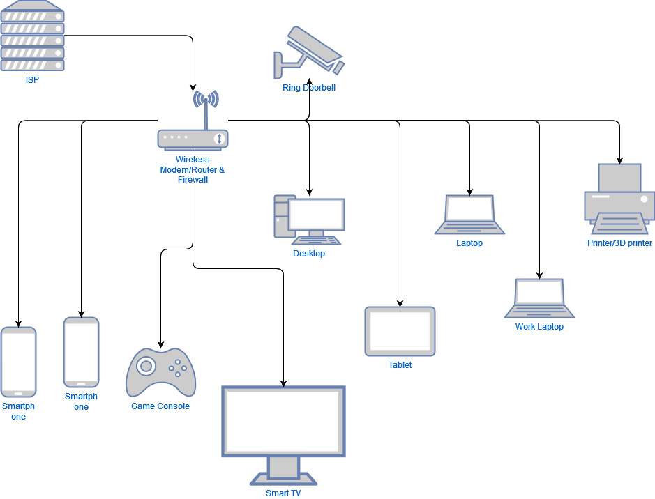
Here we have an ISP (Internet Service Provider) providing internet connection to a single wireless router/modem/firewall.
Then off of that singular modem/router/firewall we have all of our devices connected:
- Ring Doorbell
- Smartphones x2
- Game Console
- Smart Tv
- Desktop
- Tablet
- Laptop
- Work Laptop
- Printer/3D printer (both or either or)
Most homes will have more IoT (Internet of Things) devices in the future. So that diagram could be expanded to include, thermostats, light bulbs, fridges, cars, chargers, and other sensors.
Problems?
Looking at the diagram above what issues do you think there are?
- No Security - if one device gets compromised it’s very easy to move within that network and take over all of your devices.
- No Privacy - most smart devices or IoT devices ping other devices in your network and send that data back to the cloud. They can track what you watch, when you’re home, what devices you have, how many people are in the home, what you buy, when you buy it, and more.
- At risk for being hacked - since all the devices on this network have internet access, it doesn’t take much for someone to find a vulnerability and exploit it within your network.
- No Segmentation - with all the devices being on the same “network” anyone can take over one device and then take over all the devices.
- Anyone can just join - The lack of a guest network allows anyone who has the password to just connect to your network and could potentially infect your devices.
- Single Failure Point - If your main firewall/router/switch goes down you then loose network connection for all of your devices. (this might not be an issue for most home users but its worth pointing out)
- Potential for slower speeds - since all devices are on the same network there is potential for network bottlenecking/traffic issues causing slower speeds on that singular network.*
Mitigation
So now that we know what the issues are for that network, how can we mitigate it? There are a few approaches we can take. It all depends on your own use cases and how in-dpeth you wish to go.
- Segmentation: Ideally we should aim to segment the network into different areas. Group devices into different categories/levels of trust.
- Isolation: When segmentation isn’t enough, we want to isolate devices. This will allow us to cut off access going in and going out of some devices. Isolation should be used in conjunction with segmentation.
- No Default LAN - When you first setup a network all devices automatically connect to the “default LAN”. This means if someone where to just plug a device into your network they could bypass your segmentation. By removing the default LAN or changing how its setup your can mitigate this issue.
- Firewall Rules - Most home routers/firewalls/modems should have some type of firewall configuration, however it is recommended that you replace what the ISP gives you with some commerical alternative. Setting up firewall rules further allows you to secure your network from within.
Enhanced Home Network
So now that we know how to mitigate some of the issues we had in our first diagram, lets see what an improved home network would look like.
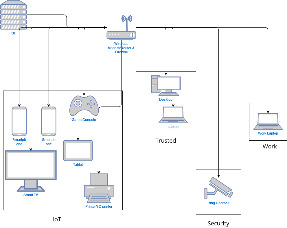
We still have the same ISP and singular wireless router/modem/firewall for now but we have grouped devices into different blocks. These blocks are called VLANS or Virutal Local Area Networks.
Now we have the following groups containing our devices
| VLAN | Devices |
|---|---|
| IoT | Smartphone |
| IoT | Smartphone |
| IoT | Smart TV |
| IoT | Tablet |
| IoT | Game Console |
| IoT | Printer/3D Printer |
| Trusted | Laptop |
| Trusted | Desktop |
| Security | Ring Doorbell |
| Work | Work Laptop |
Each item is grouped together based on a few different criteria.
- Trust - is this a device that I control and can trust?
- Noise - does this device reach out to the internet or ping my network?
- Security - will this device be a threat if compromised?
- Knowledge - should this device know about other devices on my network?
Additional Criteria
If your devices have management interfaces or web UI portals that you can connect to, you may want to add an additional VLAN dedicated to hosting those portals. You may or may not be able to change where those portals are hosted. We will not cover that specifically in this tutorial but it is something to consider.
Planning
So now that we’ve seen the “enhanced home network”, how do we build it?
Well first thing is to group devices into categories or levels of trust.
Think about the level of permissions each device should have:
- Should they know about all devices on my network?
- Should they reach the internet?
- Should I be able to reach them while inside my network?
- Should a guest be able to reach them while inside my network?
Don’t think too hard about this because you can easily overwhelm yourself. Start off simple and then get more granular as you slowly improve your skills and experience.
Here are a few examples of VLAN’s and their descriptions:
- IoT – least amount of trust. Most “smart devices”, which includes TV’s, fridges, thermostats, sensors, and phones.
- Work - work computer that should not have access to anything but the internet
- Guest - no access to anything but the internet
- Security – high amount of trust, no internet access
- Management – management interfaces of networking devices. Web UI’s. Limited access from within the network.
- Trusted – Desktop or laptop computers that need to access to management interfaces
Things to Note
- Just putting devices into VLAN’s does not make them more secure.
- Firewall rules will need to be setup.
- You will probably need more hardware.
- A network switch was not included in the diagram above. But it is a requirement for setting up a secure network.
- Take notes of your configurations!!
- There is no 1 correct way.
Hardware and Software
So now that we’ve seen what we can do and how to start planning for it. Lets get into what we need to get started.
First off, if you just have a router/modem combo from your ISP you will need to get a new device.
A list of some basic hardware required:
- Modem - if your ISP requires a modem in order to connect to the internet this will be the first device in your network chain.
- Router - if the ISP has an ethernet line coming into your home you can use this to connect to the internet. Ideally you’d want a hardware firewall first, but if the router has firewall software on it this will be fine.
- Firewall - A separate firewall can be a good idea to help limit the responsibility of one device, but this does add more devices/power consumption to your home network and it can be more to manage.
- Managed Switch - a simple 8 port managed switch is necessary for setting up your VLAN’s
- Wireless Access Points (WAPs) - having separate WAP’s will make segmenting your Wi-Fi easier.
The table below will contain a list of devices from least expensive to most expensive.
| Price Ranges | Router | Switch | WAP |
|---|---|---|---|
| Least Expensive | TpLink Archer A7 | TP-Link 8 Port Switch | TP Link EAP225-V3 |
| Mid Priced | Ubiquiti UniFi Dream Router | Netgear 8 Port Switch | TP Link EAP610-V2 |
| Most Expensive | Protectli Vault | Netgear 16 Port Managed POE Switch | Ubiquit Unifi 6 Pro |
Software Involved
Some routers can support being flashed with different software. But for the sake of this tutorial we will be covering a few different software packages for routers that you can use.
Router
- Default - the default software that ships with your device can usually get the job done most of the time.
- OPNSense - This software is free and can be installed on a wide variety of x86 based devices.
- PFSense- An alternative to OPNSense. PFSense and OPNSense are based off OpenBSD and share a very similar codebase. Each one has a few different features that may fit your needs differently
- OpenWRT - Open source router software that can be flashed onto a wide variety of devices. Including but not limited to arm devices such as raspberry pi’s, commercial routers, and x86 hardware machines.
- DD-WRT - Another popular option, but falls behind OpenWRT in widespread adoption.
Switch
- Default - To my knowledge, the default switch software is all that’s available to use on any device that you buy.
WAP
- Default - Most WAP’s come with a good suite of software to manage and control the devices
- OpenWRT - It is possible to purchase inexpensive routers, flash OpenWRT onto them and use the device in Access Point Mode to extend your wifi range.
Configuration
So now that we’ve seen the ehnaced home network model, we’ve planned how we want to group our devices together, we’ve gathered our hardware and software we are ready to start configuration.
We are going to go over a few different steps. Lets talk through what we will be accomplishing first.
These steps are universal across different vendors. I will be using PFSense and a TPLink switch as an example through this tutorial, but the same principles should apply with any other vendor.
- We need to create a new VLAN on the firewall/router
- Each VLAN will need an Tag, Name, Description and IP address range
- For simplicity we will be using
192.168.x.1where thexor third octet of the IPv4 range is the same as our VLAN Tag. Ex: VLAN Tag 150 -> 192.168.150.1
- Each VLAN will then need to be assigned to an interface.
- Depending on your router/firewall you may be able to put all VLAN’s on 1 interface or you may need to put them on different interfaces. Some firewall/routers support virtual interfaces others do not.
- We will need to create a DHCP server for each VLAN to give out IP addresses to the devices that we want to be associated with those VLANs.
- Our switch will need to also know how to send traffic. We will have to configure VLANs on there as well.
- Some devices will be VLAN aware and others will not be. That will determine how we setup our switch. (More on that later)
So lets start off with the firewall.
Firewall Config: PFSense
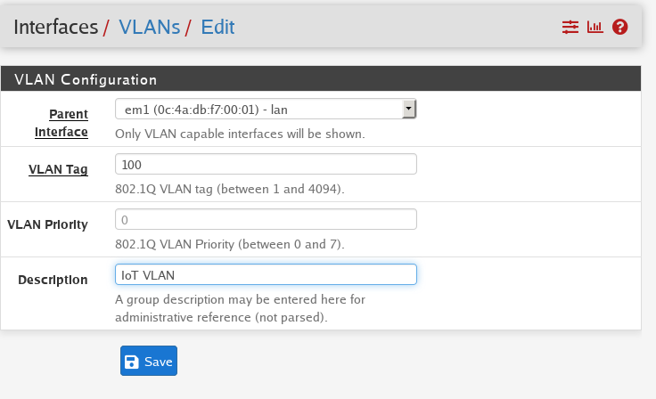
First lets create a new VLAN
- You will need a name:
IoT - VLAN tag:
100 - Description:
Internet of Things Network - Interface to assign this to:
eth0, igb0, wlan0, etc
Then we repeat for each VLAN
Make sure you take notes of these configurations!!
VLAN Config: PFSense
Following the steps above in PFSense for example we can begin to setup our VLAN
Then we repeat the process until we have all the VLAN’s configured
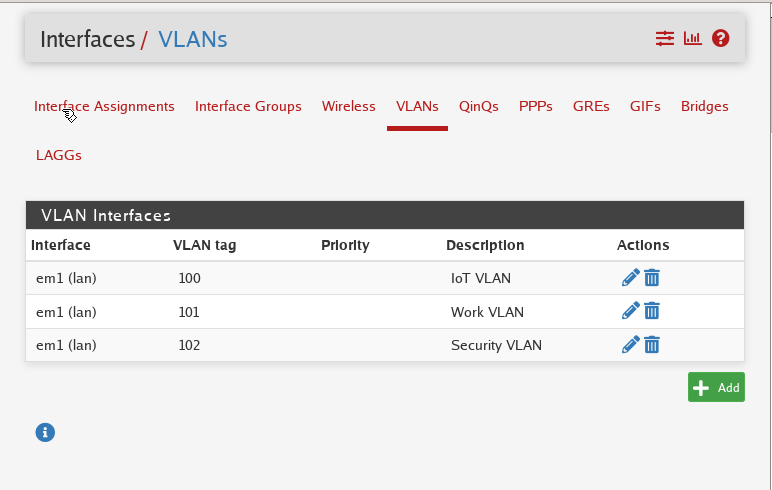
Here we have the following:
| VLAN | Tag | Description |
|---|---|---|
| IoT | 100 | IoT VLAN |
| Work | 101 | Work VLAN |
| Security | 102 | Security VLAN |
Interface Assignment
After creating the VLAN’s you may need to assign them to an interface. If you have multiple network interfaces you can assign multiple VLAN’s to each one. (Depending on software vendor) Ex:
- Eth0 – IoT, Lab VLANs
- Eth1 – Security
- Eth2 – Guest, Work
- etc
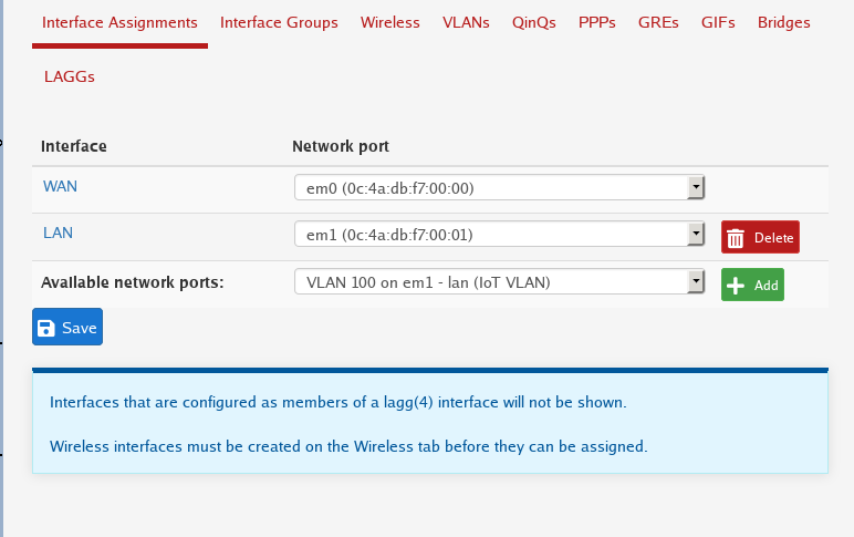
In the image above, under the LAN section there’s a dropdown menu allowing us to add another interface assignment. First we select VLAN 100 and then click add.
Once we’ve done that we can repeat the process for all the other VLAN’s.
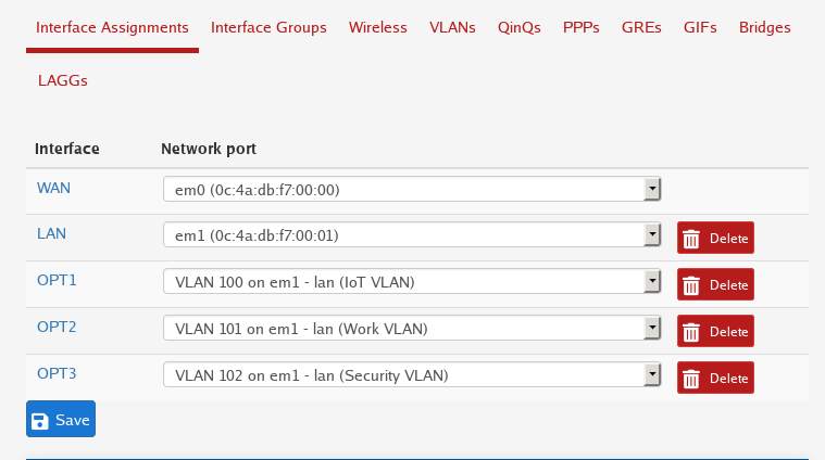
Next you will have to configure the newly assigned interfaces.
Right now we’ve only told the firewall that we want a new VLAN, the VLAN has a tag (id), a name, and a description. We also assigned it to a virtual interface. We still need to configure a few more things.
Each VLAN will be assigned its own IP address range and its own set of firewall rules.
Interface Config
A new Interface will look like this
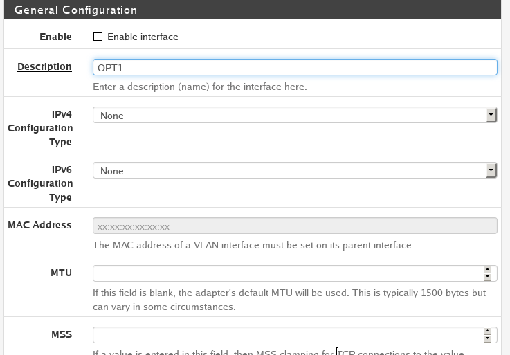
We will need to modify it to match how we setup our VLAN
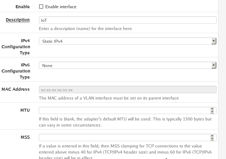
- We will have to enable the interface
- We want to change the name of the interface from the interface name to the VLAN name
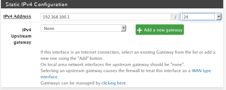
- Set the IPv4 Config type to Static. This way we can manually assign an IP address range to this VLAN. For this VLAN we will set the IP range to
192.168.100.1/24.- /24 is CIDR notation and means IP addresses from
192.168.100.0-192.168.100.256. Depending on how many devices you plan on having on your network you can reduce the number of allowed IP address by changing the number after the slash/. But refer to the CIDR documentation to make sure you understand what to do.
- /24 is CIDR notation and means IP addresses from
To make things simple we can make the 3rd octet of the IP address range the same as the VLAN tag.
Ex:
| VLAN | ID | Description | IP Range |
|---|---|---|---|
| IoT | 100 | IoT VLAN | 192.168.100.1/24 |
| Work | 101 | Work VLAN | 192.168.101.1/24 |
| Security | 102 | Security VLAN | 192.168.102.1/24 |
DHCP Server
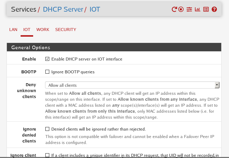
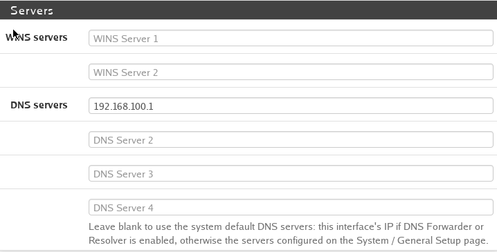
Following the screenshots above lets walk through what we are configuring.
Each VLAN will need a DHCP server to give out IP addresses to devices that are connected to it.
- The DHCP server will need to be enabled.
- You can configure it to only allow “known clients” via MAC addresses but for this tutorial we will Allow all clients
- Leave the Ignore Denied Clients and Ignore Client checkboxes unchecked.
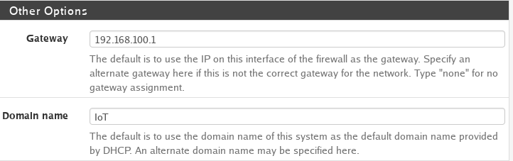
- Then we need to setup a gateway. The gateway is the route that the DHCP server takes to get to the internet. For each DHCP server it will be as follows:
192.168.x.1replace the x with the VLAN Tag. - Give the Domain a name. Usually I put the VLAN name for clarity.
- Next you can set the DNS server to be the same as the Gateway.
192.168.x.1(replace the x with the VLAN tag)
Repeat this process for each VLAN you have. When you are done you should have the following setup.
| VLAN | ID | Description | IP Range | DHCP | DNS |
|---|---|---|---|---|---|
| IoT | 100 | IoT VLAN | 192.168.100.1/24 | 192.168.100.1 | 192.168.100.1 |
| Work | 101 | Work VLAN | 192.168.101.1/24 | 192.168.101.1 | 192.168.101.1 |
| Security | 102 | Security VLAN | 192.168.102.1/24 | 192.168.102.1 | 192.168.102.1 |
Once each VLAN is assigned to an interface you will now need to setup firewall rules.
Firewall Rules
The rules below are an example for how I normally segment a simple network.
Rules:
- Block Firewall access
- Block RFC1918 Networks
- Allow Internal DNS
- Block External DNS
- Allow All
So what do these rules do?
- Each VLAN should not be able to access the firewall itself. We want to reserve access to only the trusted or management VLAN’s that we plan on setting up.
- Blocks access to all private network addresses. RFC1918 is a specification for internal IP addresses. By blocking access to those ranges any device that is connected to one VLAN cannot communicate to a different VLAN. Ex: VLAN 1 can only talk to VLAN 1. VLAN 2 cannot talk to VLAN 1, etc.
- Allow internal DNS. Since we setup the firewall to be our DNS resolver, we need to allow traffic to it in order to get internet access.
- This rule may differ if you are using different software. You can omit this rule entirely if you are unable to access the internet.
- Blocks external DNS. Ex: 8.8.8.8 (Google). By blocking External DNS we can prevent devices from communicating with a DNS server that we did not specify.
- This rule may differ if you are using different software. You can omit this rule entirely if you are unable to access the internet.
- Allow all other traffic not specified. This rule is usually the last rule we set it. It allows traffic anywhere as long as we did not already block it above.
These are a set of basic rules that we have setup. But you can get more granular for each VLAN.
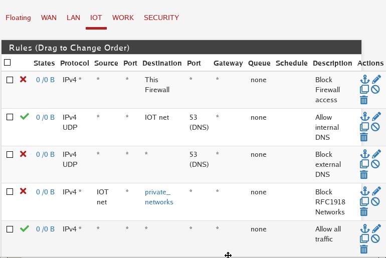
Ex IoT Firewall Setup:
You can repeat these steps for each VLAN that you have setup.
Table Key:
- “*” - anything
IoT
| Rule | Protocol | Source | Port | Destination | Port | Description |
|---|---|---|---|---|---|---|
| Block | IPv4 | * | * | This Firewall | * | Block Firewall Access |
| Allow | IPv4 | * | * | 192.168.100.1/24 | 53 | Allow Internal DNS |
| Block | IPv4 | * | * | * | 53 | Block External DNS |
| Block | IPv4 | 192.168.100.1/24 | * | RFC1918 Networks | * | Block RFC1918 Networks |
| Allow | IPv4 | * | * | * | * | Allow All Traffic |
Work
| Rule | Protocol | Source | Port | Destination | Port | Description |
|---|---|---|---|---|---|---|
| Block | IPv4 | * | * | This Firewall | * | Block Firewall Access |
| Allow | IPv4 | * | * | 192.168.101.1/24 | 53 | Allow Internal DNS |
| Block | IPv4 | * | * | * | 53 | Block External DNS |
| Block | IPv4 | 192.168.101.1/24 | * | RFC1918 Networks | * | Block RFC1918 Networks |
| Allow | IPv4 | * | * | * | * | Allow All Traffic |
Security
| Rule | Protocol | Source | Port | Destination | Port | Description |
|---|---|---|---|---|---|---|
| Block | IPv4 | * | * | This Firewall | * | Block Firewall Access |
| Allow | IPv4 | * | * | 192.168.102.1/24 | 53 | Allow Internal DNS |
| Block | IPv4 | * | * | * | 53 | Block External DNS |
| Block | IPv4 | 192.168.102.1/24 | * | RFC1918 Networks | * | Block RFC1918 Networks |
| Allow | IPv4 | * | * | * | * | Allow All Traffic |
The example firewall rules above should give you an easy guideline to get started. Each software is different in how they are able to setup firewall rules, but the same principles should apply across the board.
Switch Configuration
There are a few terms we need to get familiar with when it comes to switches.
- 802.1Q VLAN
- VLAN Tagging
- Tagged vs Untagged
- PVID
Tagged ports: usually “trunked” connection. Connect 2 switches together. Also they “tag” the VLAN ID/Tag to the packet that is getting sent across the port to its destination.
Untagged: no VLAN identifier is attached to the packet.*
VLAN Tagging: this adds the ID of our VLAN to the data packet that gets sent over the network
PVID: Port VLAN ID
Lets take a look at how we would wire up our switch and what the configuration would look like.
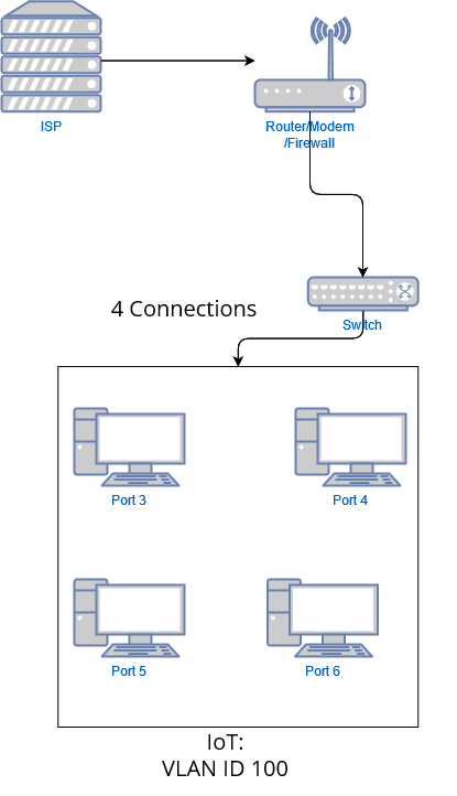
In this diagram we have our main Router/Modem/Firewall. Then we have a single ethernet cable connecting to port 1 of our switch.
From the switch we will have the following
- Port 3 is connected to computer 1
- Port 4 is connected to computer 2
- Port 5 is connected to computer 3
- Port 6 is connected to computer 4
Then we will have the following config:
| VLAN ID | VLAN Name | Member Ports | Tagged Ports | Untagged Ports |
|---|---|---|---|---|
| 1 | Default | 1-8 | 1 | 1-8 |
| 100 | IoT | 1,3-6 | 1, 3-6 | - |
The table above is a generic configuration setup for TPLink switch. However, much of the information here can be applied to other switches.
Here we are setting the ports to be tagged since the devices that we are connecting are VLAN aware. Also, it specifies that the traffic coming over those ports should be going to specific VLANs. We also add Port 1 to the IoT VLAN so that the IoT VLAN can reach back to the main router/firewall/modem to get internet access.
Repeat the process for the other VLANS we configured
| VLAN ID | VLAN Name | Member Ports | Tagged Ports | Untagged Ports |
|---|---|---|---|---|
| 1 | Default | 1-8 | - | 1-8 |
| 100 | IoT | 1,3-6 | 1,3-6 | - |
| 101 | Work | 1,7 | 1,7 | - |
| 102 | Security | 1,8 | 1,8 | - |
Then the PVID setup would be as follows
| Port | PVID |
|---|---|
| 1 | 1 |
| 2 | 1 |
| 3 | 100 |
| 4 | 100 |
| 5 | 100 |
| 6 | 100 |
| 7 | 101 |
| 8 | 102 |
- By setting the PVID for port 3-6 we associate traffic along those ports to VLAN 100 (IoT).
- Same for port 7, all traffic along that port belongs to VLAN 101 (Work)
- Same for port 8, all traffic along that port belongs to VLAN 102 (Security)
NOTE some switches have different configurations, menus and options. You can follow this guide to get a general idea of how to plan different VLANs. Ultimately it is suggested to follow the documentation for the specific vendor of your switch.
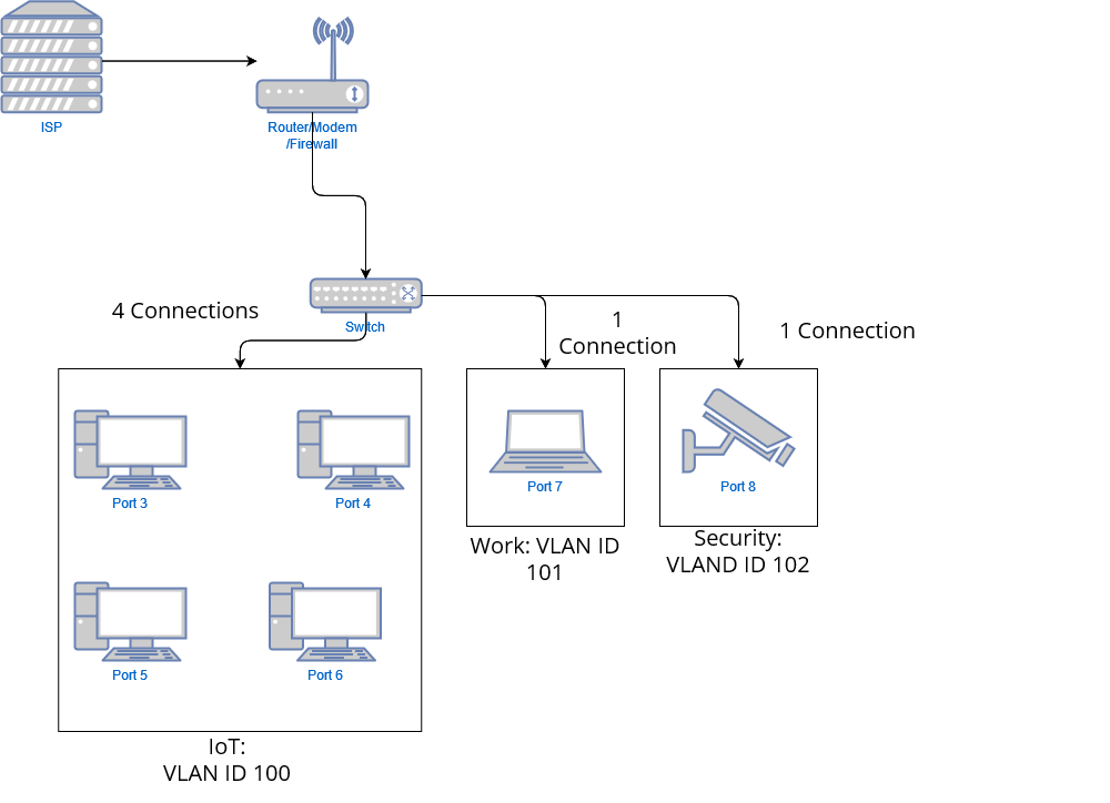
Switch Example with WAP
The previous diagrams details connections that were directly wired to a network switch. But as we all know, not all devices are hard wired and they require Wi-Fi to be able to connect to the network and access the internet. So given our first example of our modified home network, lets take a look at what that would look like.
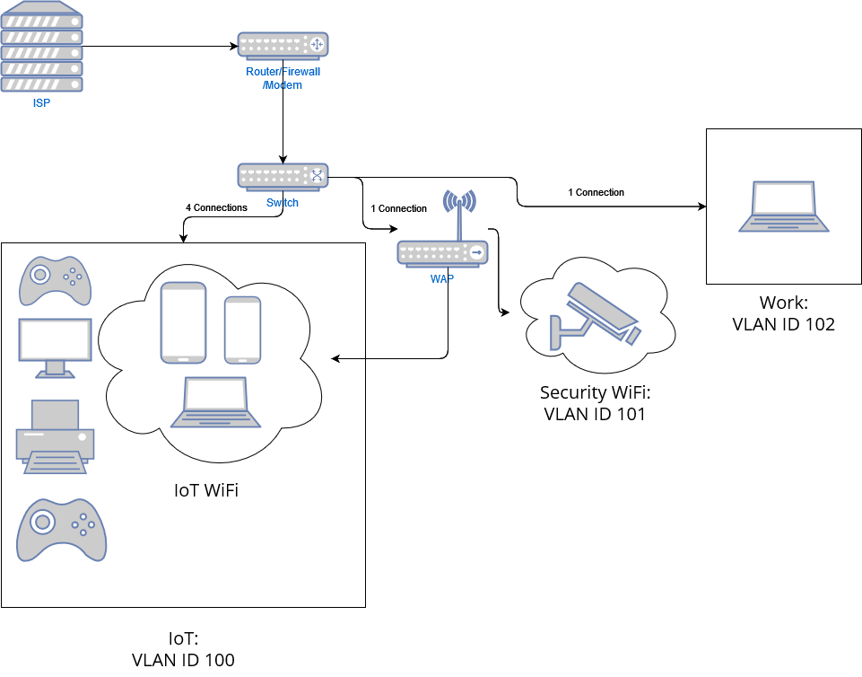
So here we still have our main connection coming in from the ISP and connecting to our Router/Firewall/modem. We also still have our switch and our main VLAN’s details out. However we added an additonal device here. This time we have a Wireless Access Point in the mix.
Starting from the left you can see we still have our IoT VLAN with the following devices:
- Game console
- Smart TV
- Printer/3D printer
- Game console
These devices are hard wired to the switch. Hence the 4 connections. The next 3 devices are nested inside the VLAN but are not hard wired.
- Smart phone
- Smart phone
- Laptop
You can see we have 1 connection coming from our switch connecting to our WAP. That main connection contains all the VLAN ID’s we need in order to broadcast different SSID’s for devices to connect to.
Next we have the Security Wifi containing our Ring Doorbell and last we have the work VLAN which is still hardwired to our switch.
So lets take a look at how our switch config will differ in this new setup.
| VLAN ID | VLAN Name | Member Ports | Tagged Ports | Untagged Ports |
|---|---|---|---|---|
| 1 | Default | 1-8 | - | 1-8 |
| 100 | IoT | 1-6 | 1-6 | - |
| 101 | Work | 1,7 | 1,7 | - |
| 102 | Security | 1,2,8 | 1,2,8 | - |
Now the IoT and Security VLAN contain port #2 which gets connected to the WAP.
Then the PVID setup would be as follows
| Port | PVID |
|---|---|
| 1 | 1 |
| 2 | 1 |
| 3 | 100 |
| 4 | 100 |
| 5 | 100 |
| 6 | 100 |
| 7 | 101 |
| 8 | 102 |
After you’ve connected the WAP to the switch you will have to configure the different VLANs on your Wi-Fi access point. Typically you can create a new network off of the VLAN ID. You will then have to setup a password and SSID. This will differ based on your network device.
Make sure you make a backup of your configuration and document where cables go before you begin to make changes to your network.
Conclusion
This was the first entry in the Home Security Series and I hope you were able to learn valuable information and will stick with us while we dive into other topics about securing your home and home network.
This post is just the tip of the iceberg into your security and cyber security journey. However, don’t let this discourage you from at least adopting these simple best practices! Some of you will go beyond this post and icorporate more advanced techniques while others will just do the basics. Both options are fine, but I encourage you to at least learn the basics when it comes to protecting your home network so that you are better prepared in the event something gets compromised on your network.